
Troubleshooting
When your Carrier Vibrating Equipment isn’t performing at its best, professional troubleshooting helps pinpoint the root cause before small issues turn into costly downtime. Our technicians combine deep product knowledge with real-world experience to get your equipment back to peak efficiency, safely and reliably.
Reliability & Uptime
Carrier understands that the quality of our After-Sales Service can be a strong indicator of total customer satisfaction. We view aftermarket service with the importance that it deserves.
If you’re experiencing a problem, our product knowledge and decades of collective experience can help minimize downtime and inconvenience. Explore the troubleshooting resources on this page for guidance and support. If you cannot find the help you need, please contact us directly, and our team will be ready to assist you.
To help identify the problem, our Service Manager will ask general questions, as outlined in the Troubleshooting Equipment Reference below. For further technical assistance, inquiries should be directed to:
Troubleshooting Equipment Reference
What is the serial number of the unit?
The serial number of the unit can be found on the data tag in the drive area and it is also stamped in the end of the drive shaft opposite the driven sheave. Each piece of Carrier equipment is custom designed. The serial number is our identification number for parts lists, drawings, operational manuals, etc. The serial number can also be found on the lower right-hand corner of the final certified drawings included in your Installation & Operational Manual. A typical serial number will be a five-digit number, i.e. S/N 27111.
What is the unit’s stroke?
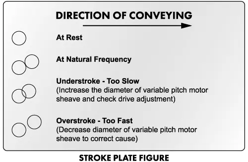
Check the stroke by locating and reading the stroke plate. Refer to the Stroke Plate Figure below. The unit’s stroke should closely match the stroke listed in your Installation & Operational Manual. The stroke plate is a decal or magnetic plate attached to the pan, counterbalance, base or exciter. The diameter of the circle represents the length of stroke. For example, a unit with a 1” stroke would use a stroke plate with a 1″ diameter circle. With the unit in operation, two circles will appear when looking at the moving stroke plate. When the two circles are exactly tangent in the form of a figure 8; the unit is set to its proper natural frequency speed.
If a stroke plate cannot be found on the unit or if it has been painted over and is no longer legible, a temporary stroke plate can be made by using a template to draw the appropriate size circle on a piece of paper or cardboard, which can then be taped or glued on the side of the vibrating member to be measured.
Has any weight been added or removed from the unit?
The addition or removal of any weight to the vibrating member must be countered by adjusting the speed and/or spring system. Please consult Carrier before adding or removing any weight to your unit.
Is the spring count correct, and are the spring bolts properly torqued?
The addition or removal of springs will have a direct effect on the stroke, this includes broken or loose springs. Please refer to your final certified drawing for the correct spring count.
Has any work been completed to the drive recently?
Drive work must be completed as outlined in the Installation & Operational Manual. Typically when drive components are replaced, proper drive timing is overlooked, resulting in hard starts, high amp draw, and short bushing or shock absorber life.
What is the drive shaft RPM?
Increased or reduced drive shaft RPM will correspondingly increase or reduce the unit stroke.
Typical Causes of Overstroke
Typical Causes of Unerstroke
Is the unit noisy?
The presence of any noise or knocking will usually indicate loose bolts. These may be spring, drive, anchor, cover or stabilizer bolts. Also, check for loose setscrews holding the sheave and bearings to the drive shaft. However, other problems, such as overstroke and understroke, may be involved.
What problems are you experiencing?
Be prepared to give a brief summary of the problem before calling, while answering as many of the above questions as possible.
What is the serial number of the unit?
The serial number of the unit can be found on the data tag in the drive area and it is also stamped in the end of the drive shaft opposite the driven sheave. Each piece of Carrier equipment is custom designed. The serial number is our identification number for parts lists, drawings, operational manuals, etc. The serial number can be found on the lower right-hand corner of the final certified drawings located in your Installation & Operational Manual. A typical serial number will be a five-digit number, i.e. S/N 27111.
What is the unit’s stroke?
Check the stroke by locating and reading the stroke plate. Refer to the Stroke Plate Figure below. The unit’s stroke should closely match the stroke listed in your Installation & Operational Manual. The stroke plate is a decal or magnetic plate attached to the unit. The diameter of the circle represents the length of stroke. For example, a unit with a 3/16″ stroke would use a stroke plate with a 3/16″ diameter circle. With the unit in operation, two circles will appear when looking at the moving stroke plate. When the two circles are exactly tangent in the form of a figure 8, the unit is set to its proper natural frequency speed.
If a stroke plate cannot be found on the unit or if it has been painted over and is no longer legible, a temporary stroke plate can be made by using a template to draw the appropriate size circle on a piece of paper or cardboard, which can then be taped or glued on the side of the vibrating member to be measured.
What is the unit’s angle of attack?
The angle of attack can be determined by reading the approximated angle of the two circles in motion, i.e. 45 deg. to 90 deg. The angle of attack affects the product conveying speed as well as drying and cooling. The correct angle of attack can be found on the final certified drawings. The procedure to achieve the correct drive-timing angle can be found in your Installation & Operational Manual.
What process problems are you experiencing?
Be prepared to give a brief summary of the problem before calling. The typical information requested during the troubleshooting process is as follows:
How do I read a stroke plate?
Contact Carrier’s Service Department at +1-502-969-3171 extension 226 if you need assistance.
Used or Non-Carrier Equipment
We offer our services to recondition used Carrier vibratory equipment as well as non-Carrier or competitive vibratory equipment for a fixed fee. Fee to cover services of a Field Service Technician on site for inspection, a complete Installation and Operation Manual, detailed drawings, recommended spare parts lists, and formal trip report outlining findings and recommendations as required. Please contact our Service Manager for current rates and policies. Call us today with your questions.
After Hours Emergency Contacts
The Service Department is available for emergency consultation 24 hours a day, seven days a week, including holidays.
For emergency parts or emergency service assistance, call +1 (502) 969-3171 and follow the prompt. Assistance Instructions will include the Aftermarket Manager and Service Manager’s cell number for 24/7 contact.